
What Are Bandpass Filters?
How Does the Angle of Incidence Affect Wavelength Shift?
How Does the Angle of Incidence Affect Wavelength Shift?
The central wavelength of the all-dielectric Fabry-Perot filter will shift lower in wavelength with an increase in the incident angle. The amount of wavelength shift is dependent upon the incident angle and the effective index (N*) of the filter. This feature can be very useful in tuning a narrowband filter to the desired central wavelength. The following formula may be used to determine the wavelength shift of a filter in collimated light with incident angles up to 15 degrees:
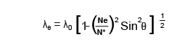
Where:
- λθ = Wavelength at angle of incidence
- λ0 = Wavelength at normal incidence
- Ne = Refractive index of external medium
- N* = Effective refractive index of the filter
- θ = Angle of incidence
When an optical bandpass filter is used with non-collimated light such as convergent or divergent rays, the wavelength shift will appear somewhat less than that of collimated light at the same angle. In a cone of light, only the central ray is normal to the surface, and all others are increasingly off-angle. The resultant shift could be given by integrating the wavelength shift over the range of angles, but this is a rather lengthy process. A good approximation of the shift can be made by using the previous formula and dividing the calculated shift by two. This will work in systems where the full cone angle is a maximum of 20°.
Wavelength Shift With Temperature
What Is the Bandshape of Optical Bandpass Filters?
Due to the fact that the Fabry-Perot filter is essentially Lorentzian in shape, the cut-on and cut-off slopes are very shallow, and the rate of attenuation in the out-of-band blocking range is very slow. To improve the slopes and increase the attenuation in the blocking band, we introduce more cavities into the construction. Please refer to the band shape charts for a comparison of one to four cavity filters. Please note that this data is only applicable to dielectric bandpass filters.
Another very important factor to note is that due to matching the different cavities within a filter construction, we cannot add an infinite number of cavities. Please refer to the standard and custom interference filter section of this site for the appropriate information.
How Environmentally Stable Are Optical Bandpass Filters?
All of our optical bandpass filters are stabilized to prevent drift of peak wavelength with age and are hermetically sealed for maximum humidity protection. Each filter is mounted in a black anodized aluminum ring, which affords increased protection against damage resulting from rough handling and moisture penetration. However, even with this construction, it is advisable to avoid prolonged exposure to environments in which high humidity and large temperature variations are concurrent.
How Should Optical Bandpass Filters Be Oriented?
As a general rule, the highly reflective side of the filter should always face the source of radiation. This minimizes the thermal load on the absorbing glass blocking components and epoxies, thereby extending the lifetime of the filter. Apart from the reduction of thermal effects, filter orientation has no influence on the spectral characteristics.
Summary
The effects of temperature, optical path geometry, and environmental conditions must be considered when selecting or specifying optical bandpass filters. All of our filters are designed to operate at 23°C in normal incidence collimated beams. Please consult with one of our specialists before specifying any off-normal conditions so that a filter best suited for your application can be designed.
Andover Insights & Innovations
Discovering new possibilities in optical filtering

Light Reveals the World. We Refine the View.


Contact Our Team
Ready to discuss your optical needs? Whether you're looking for a quote or have technical questions, our expert team is here to help guide you to the perfect solution.